до 200 Гц звук вобще не локализуется
можеш провести эксперимент на ленточных высококачественных
головных телефонах (в народе их называют наушниками)
телефоны разработки Львовского НИИБРА БЕЗ ПРОБЛЕМ РАБОТАЛИ В ДИАПАЗОНЕ
20 - 32000 Гц
увы НИИБРА - филиал нашего ЛНИИРТИ - ныне покойное
а ЛНИИРТИ или по инглишу LRERI - успешно работает
http://lreri.tripod.com/
вот одна из разработок
в которой я принимал участие
http://lreri.tripod.com/products.html
3 mm Pulse
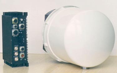
Collision Avoidance Radar (CAR)
Applications
CAR has worked out for collision avoidance tackling safety problems for small height flights of helicopters and light planes in mountain areas, in urban and industrial building areas, over agriculture lands having high voltage transmission lines.
Description
The radar is compared to a well-known similar one called ROMEO which was developed by Thomson Company (France), has considerably smaller (2.5 times) dimension and weight. This ensures simple compact installation and application of the system on super light helicopters. Along with this high resolving ability of the radar for angular data and for operating distance counts for high quality of radio location picture being very close to television.
Radar function of collision prevention is fulfilled any time of day and night, all weather conditions and under any environment (dusty, smoky), low-power emission used in radar system allows environment-friendly operation, electromagnetic compatibility, security, and noise stability.
Compact scan 3 mm radar is a completely solid-state pulse radar fast electromechanically scanning the antenna pattern of a large angle sector. The radar system was developed using highly advanced technologies in the field of SHF engineering and analog and digital signal processing devices.
The radar consists of two completed units: antenna head and signal processing and controlling unit and operates along with established helicopter devices; the terminal and gyroscope detectors.
Antenna head is composed of antenna system; devices scanning antenna pattern for azimuthal angle and area with corresponding detectors of twist-reflector position angle antenna-scan motor; antenna head stabilization device for roll with position detector and antenna-scan motor; radio transparent radome; receiving-transmitting device; and video frequency receiver. The antenna system consists of diagram building parts (feed horn; twist-reflector; and transreflector). Receiving –transmitting device includes receiving-transmitting SHF module and power supply unit for receiving-transmitting SHF module.
Signal processing and controlling unit is a digital part of the radar. It is composed of antenna actuator electronics; video processing and synchronization unit; secondary power supply unit for signal processing and antenna head controlling unit.
Wide range of operating temperatures is ensured with the help of constructive and technological innovations used in receiver development. Thermostated driving avalanche auto generator, frequency stabilization which is conducted by highly qualitative capacitor, generates a sequence of radio pulses, that are fed to avalanche diode amplifier input. Thermostabilization characteristics of this amplifier are carried out in the process of temperature correction of supplied current of amplifier stages. This transmitting device scheme, being very simple, ensures high spectrum clearance of output signals and low thermal bias of the operating frequency. Tests proved, that operating frequency thermal bias does not exceed (–10...+10) MHz in –50…+50 temperature range.
Antenna actuator mechanism and antenna contain a series of constructive innovations. These innovations allowed us to implement fast scanning of antenna pattern and to provide high electrical features. The main complexity of the work completed on optimization of antenna unit appeared to be strict weight and dimensions requirements for the radar as a whole.
The radar also has built-in test control for operational availability and improved test control from external computer.
Main specifications:
Scanning region:
for distance …………… 20 . . . 2500 m;
short-range region …….. 20 . . . 1500 m;
long-range region …... 1000 . . . 2500 m;
for azimuthal angle ……120 degrees;
for area angle ………… up to 15 degrees;
referring to targetings on area angle (programmable in the range from 1 degree to 60 degrees with increment of degree).
Scanning period (of radar picture update):
with the given scanning area dimensions:
120 degrees x1 degree (one azimuthal line)
65 . . . 70 msec;
120 degrees x30 degrees (30 azimuthal lines on area angle)
1.8 . . . 2.8 sec;
Detection distance:
high voltage transmission line wires with the diameter of 10 mm not less than 600m;
objects with surface of effective scattering >30 square m up to 2500 m;
Root-mean deviation:
from point target angle data not exceeding 0.5 degree;
angle range of targeting for area angle and roll given
- built-in or external detectors;
Consumed power:
(with no terminal) …. About 80 Watts
supplied voltage …... 22 . . . 30 V
Design:
Antenna head
diameter ..................... 320 mm;
length ......................... 420 mm;
weight ........................ about 15 kg.
Characteristics of constituents:
Antenna
polarization is linear horizontal or vertical;
gain in main lobe ............... 42-40dB;
sidelobes level lower main lobe ...... -23 dB;
antenna pattern beamwidth ........ 55' ... 65';
beam scanning velocity ........... up to 2000 deg/sec;
Transmitter
pulse with avalanche diode,
output power of a pulse is not less than 10 W,
pulse duration .............. 30 ... 100 nsec.
Receiver
super local oscillator with logarithmic
amplitude characteristic,
noise ratio .................... not exceeding 11 dB;
Processor
microcomputer ADSP 2181
FPGA Xilinx
two external exchange channels RS 232
RS 485 with exchange rate 38 115 kbot;
Terminal
PC based, type is defined by the installation site and customer requirements,
configuration:
similar to Pentium 166, RAM 15 Mb, hard disk 1 Gb, display 640x480 pic,
256 colours.


