Вот еще хороший
пример когда проблемы с питанием +5V приводили к появлению кракозябр.
Проблема была даже не в самой шине питания 5V, а в модуле генерации импульса ресета памяти в состояние "read-only" (чтоб не запортить ее содержимое) в момент вкл/выкл питания.
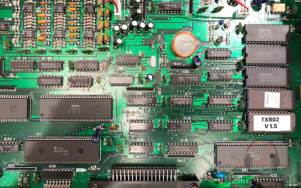
Проблема была с DX7, но в TX802 тоже есть аналогичные цепи ресета памяти, с одним отличием - вместо транзисторной сборки (Tr1,Tr2 на выходе из PSU шины 5V в схеме DX7) там стоит чип IC61 (PST518), который и генерирует сигнал ресета при падении напряжения +5V (в момент выключения).
> I'm having trouble with RAM corruption on my DX7. The
RAM test passes fine when the DX7 is powered up. If I leave it on, the RAM seems to works fine. The CR2032 battery voltage is good. The
PSU voltages also appear good.
The
corruption only seems to happen when the DX7 is powered down. The symptom is
corrupted names for patches and corrupted patches themselves (strange sounds!). I have tried swapping all three RAMs with new ones and the problem remains.
Bruce Wahler> I suspect that your battery backup circuit works, but not 100% of the time, or the voltage getting to the static RAMs is less than optimal. Here are some things to try:
- To confirm the battery,
are you measuring the battery itself? If so,
try measuring [the voltage on]
the static RAM ICs themselves. If you see less than about 2.5V, then the battery might not be making proper contact.
- There is probably
a blocking diode [диод D2 на схеме TX802] in the path between the battery and the ICs, to prevent the 5V power during operation from trying to charge the battery. At the small currents involved here, the
diode shouldn't drop the voltage more than maybe 0.2-0.3V. If it does, then either the diode is bad, or something is drawing a lot of current (which would use up the battery quickly).
Richard Brinkerhoff> The DX7 has
a power-down / Initial clear circuit which is designed to force the memory into a read-only state as power is going down and coming up. It sounds like this is what is failing.
1) The
circuitry starts with Tr1, Tr2 on the power supply board [в схеме DX7;
на TX802 вместо транзисторов стоит чип IC61]. If you have an oscilloscope, check what the PD (power down) point is doing.
It should go to near 0 volts during power down, before the +5 supply drops below 4.5 volts. On power up it should start at near 0 volts and rise after the +5 bus reaches at least 4.5 volts.
2) The next part of the circuitry is
the Initial Clear circuit, which generates the reset and write protect signals. On the schematic, the transistors involved are labeled Tr2 and Tr4, but I can't tell which board they are on.
It transforms the power-down signal into crisp reset signals. The signal labeled /IC should jump to 0 volts before the +5V buss drops below 4.5V on power down, and should remain at 0 volts until after the +5v buss reaches at least 4.5V.
3) The final part of the circuitry is
the memory protect circuit. On the schematic
it is located next to the backup battery and consists of transistors labeled Tr1, Tr3 [в схеме DX7;
на TX802 это транзисторы Q1, Q2]. The
collector of Tr3 will be near 0 volts when the DX7 is operating and should rise to between 3 and 5 volts before the +5 buss drops below 4.5 volts on power off and lower only after the +5 buss reaches at least 4.5 volts on power up. The schematic shows this connected to the /CE2 pins of the memory, forcing the memory into standby (not writable) mode during power off and power on.
Проверка модуля (Tr1,Tr2) показала что был пробит стабилитрон ZD1 (на TX802 в IC61 стабилитрон тоже есть - но внутри чипа
PST518):
> Thanks again Richard - it transpired
it was the Zener diode [ZD1 на схеме DX7]
in the PD circuit that had failed. It measured as a short circuit in both directions!
This was keeping Tr1 on all the time so the RAM CE pin was always low. I managed to source an equivalent from Maplin this morning and that seems to have fixed the RAM corruption for the time being. Hooray!
[ссылка]
В аттачменте: 1) кусок схемы с блоком ресета памяти (IC61 и Q1,Q2) и backup-батарейки (с диодом D2), 2) схема блока питания, где шина +5V питается от импульсного (switching-mode) блока (про который на форумах писали что он ненадежный)


